


Turn on the instrument by pressing the power key-press,Please replace the batteries timely when the low power symbol displayed.
1 Insulation testing:
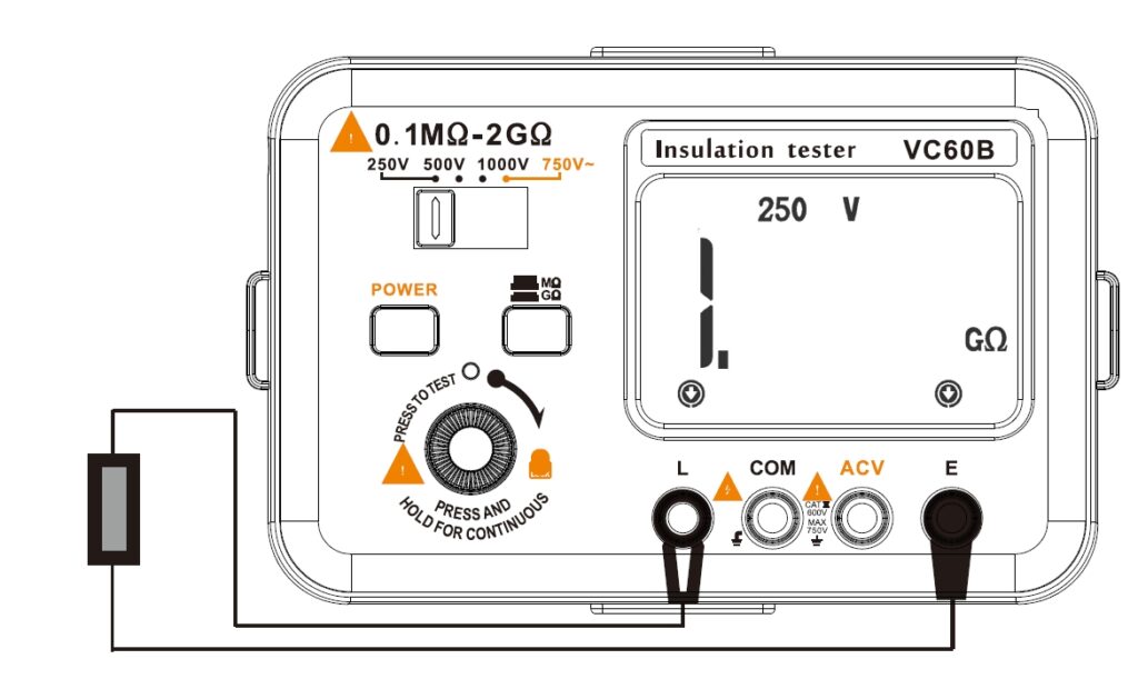
① Connect the measurand ground terminal with the input wire E, and connect the tested terminal to L.(Make the L terminal connection hand in the air as much as possible. Please connect to the COM terminal when testing for the cable.)
② According to the detecting mission, select the proper gear, then LCD will display the corresponding voltage; if the tested voltage is
unclear, try from the low gear, when it show as”1″, change to the higher gear to continue.
③ Select the proper measuring range, press the TEST key, thenthe L and E terminal will have high voltage output, LCD display symbol , the high voltage indicate light will light up.
④ Press down the TEST key to progress the measuring,readout the value when it display stable. Release the TEST key when finished, the LCD will display”1″. (lf the TEST press-key down but the LCD still display“1″, it’s
possibly cause by:
A: The tested resistance has over the selected range or over the Max. measuring range.
B: The wire maybe not being well connected or disconnected.
⑤ Press the TEST key and spin clockwise to lock and measuring continuously.
⑥ Caution: It’s prohibit from pushing/pulling the connecting wire or touching the tested resistance when the TEST key is being press down cause the L and E terminals will have high voltage output.
If the readout bing unstable all the time, it’s possible because:
A: The connecting wire is too long.
B: The humidity of the testing environment may be a little high.
C: The outer layer of the tested resistance need to be connected to the COM.
D: The tested resistance is unstable, lies in critical state.
⑦ When progressing the insulation test, please use the conductor to protect around the measurand’s ppearance between the two tested terminals in order to eliminate the aymeasuring inaccuracy which generated from the current’s leakage of the measurand’s appearance. Plus, the protected conductor should be connected to the COMterminal with the of wire.
2 AC Voltage measuring
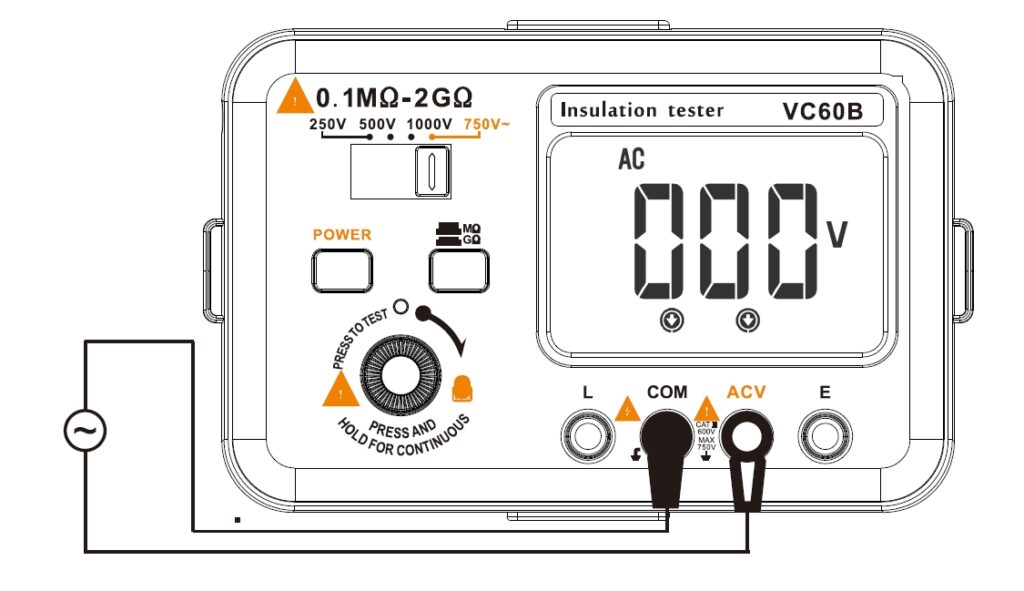
① Press the gear of 750V~, connect the ACV terminal with the red test pen, and the COM terminal with the black one.
② Full contact two tested terminals and parallel to the electric power with the testing probe. The readout on the LCD screen is the measuring result
③ lfthe LCD displayed as“000″, it indicates that the tested voltage is zero or the connected wire may be disconnected.
